← Back to Boards
Bandai Hobby Center exterior in Shizuoka, Japan.
Figure 1. The Bandai Hobby Center in Shizuoka, Japan. Bandai identifies this site as its plastic-model production base and ties it directly to four-color molding, runner recycling, and production-capacity expansion. Source: Bandai MIRAICREATION; production details: Bandai Spirits press release.

5. Injection Molding Production Process

5.1 What I Wanted to Understand

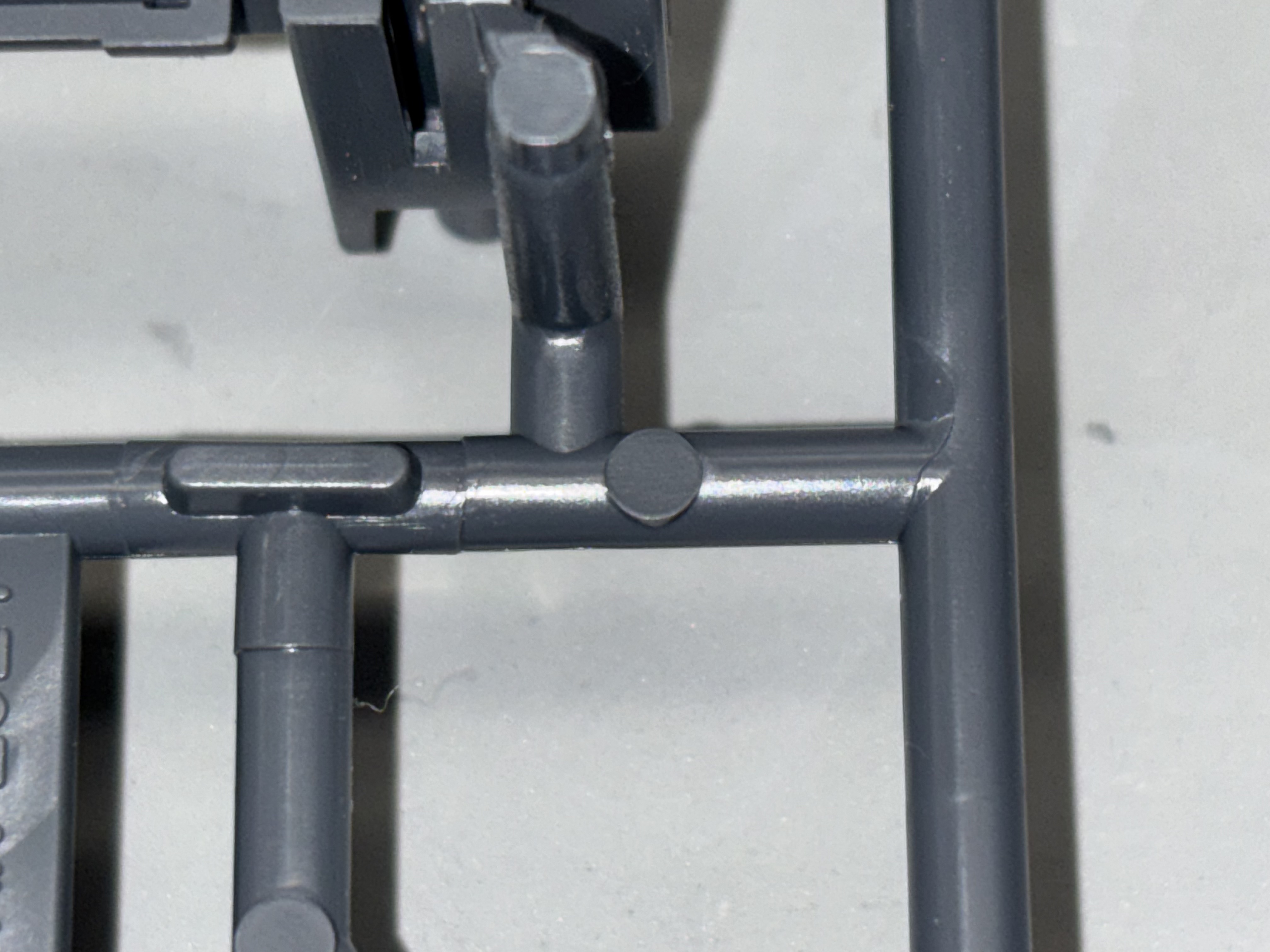
A finished armor part has razor-sharp panel lines, no visible seam, and color that goes all the way through. None of this is obvious from the consumer side. Bandai does not ship the kit with a manufacturing diagram. To understand the process, I read Bandai Spirits' published technical bulletins on the Hobby Center, peer-reviewed work on multi-color injection molding, and trade-press teardowns of the System Injection process.

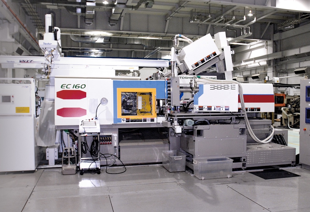
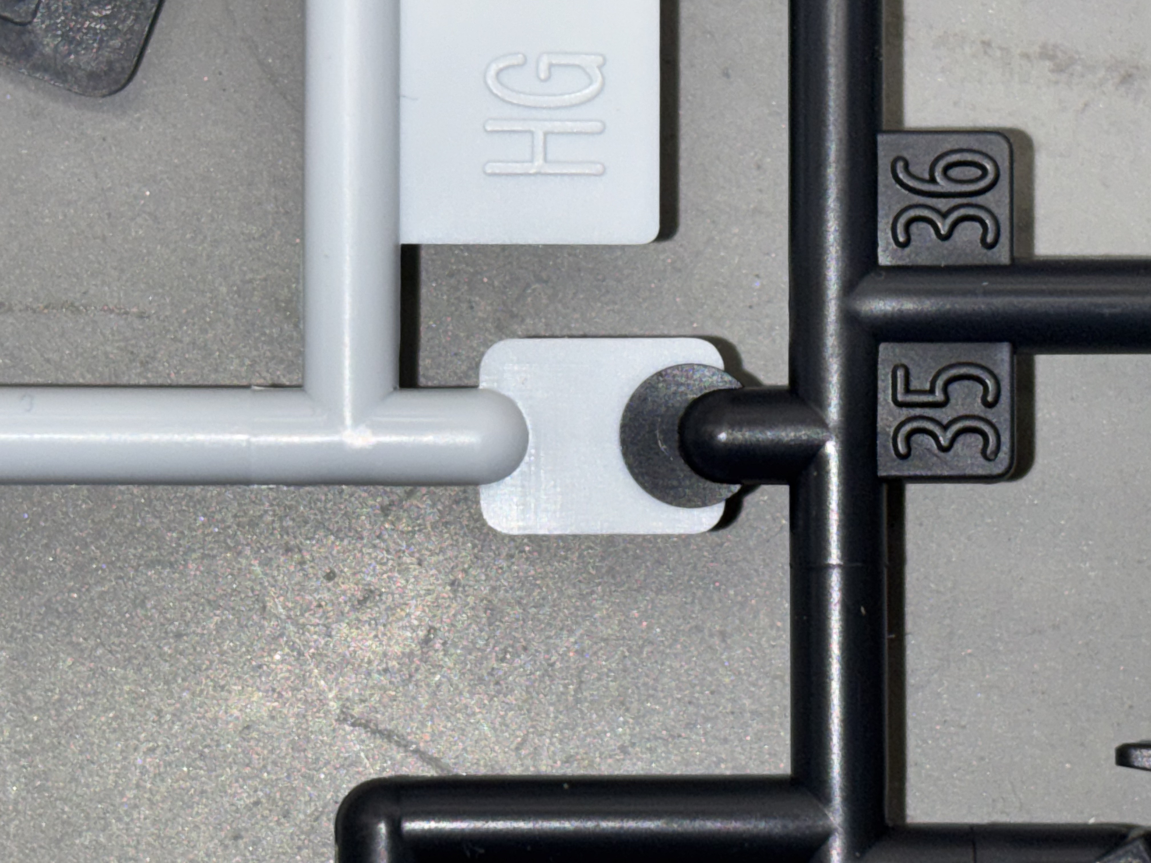
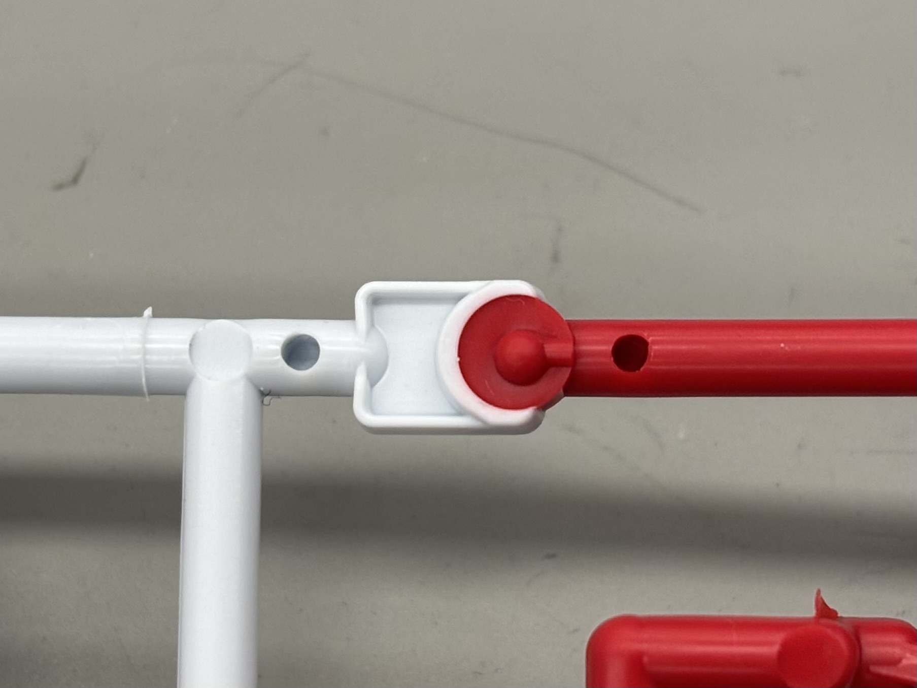
Bandai uses standard injection molding, the same basic technique used for a plastic bottle cap or a LEGO brick, but with two important extensions: System Injection multi-color molding and tightly toleranced cavities tuned for snap-fit assembly. Those two technical decisions are what enable the "no paint required" promise of an HG kit.

Close-up of a molded styrenic runner junction and gate geometry.
Figure 2. Close-up of a molded styrenic runner junction. The glossy surface and gate geometry are visual evidence of injection fill and mold-wall freezing, not an FTIR plot.
10
Multi-color molding machines planned for full FY2026 operation [Bandai]
84
Mono-color molding machines planned for full FY2026 operation [Bandai]
35%
Expected production increase versus fiscal 2023 [Bandai]
Why Multi-Color Molding?

Multi-color runners reduce packaging volume and eliminate post-processing painting!


5.2 Manufacturing Process

1
Pellet Drying
HIPS and polyethylene pellets are dried under hot air (70–80 °C for HIPS, 60–70 °C for PE) to reduce moisture below ≈0.05 wt.% before processing. Residual moisture causes surface defects and hydrolytic discoloration.
2
Plasticization
A reciprocating screw extruder melts the dried pellets at ≈200–240 °C for HIPS and ≈180–240 °C for LLDPE, building melt pressure ahead of the screw tip.
3
Injection
The screw advances axially as a piston, driving the melt through a hot-runner system into the cooled mold cavity at injection pressures typically of 50–150 MPa.
4
Multi-Color Sequencing
In Bandai's System Injection process, the mold contains gates for up to four colors. After the first color is injected, its gates close, the next color's gates open, and a different barrel injects the next polymer — cycling until the runner is complete.
5
Cooling and Ejection
Cooling channels maintain tool temperature at ≈30–60 °C; cycle times for HG-class runners are on the order of 30–60 s. Ejector pins push the solidified runner out and a take-out robot moves it to the inspection conveyor.
6
Packaging
Inspected runners are sealed in polyethylene bags with the instruction manual and decals, and the kit is boxed for shipment.
Bandai multi-color injection molding machine.
Figure 3. Multi-color injection molding machine at Bandai. The press is still the same basic melt-inject-cool system as generic injection molding, but the machine is configured around multiple material/color feeds so a single mold cycle can produce separated runner colors. Source: Bandai MIRAICREATION.

5.3 Why Multi-Color Molding Is Non-Trivial

The same mold cavity must hold molten polymer at very different bulk viscosities without bleeding color. HIPS at 220 °C has a melt viscosity roughly an order of magnitude higher than LLDPE at the same temperature, which means the gate diameters and runner geometries on a multi-color mold are tuned per polymer rather than uniformly.

The runner that emerges from the press is a single physical part with up to four colors and four materials, no painting, and snap-features molded directly into the geometry; Bandai identifies this as a capability of its original four-color injection molding machines [Bandai]. The color transitions are molded shutoff interfaces between separate shots, not paint or mixed melt fronts.

Front-side color boundary on a multi-color runner. Backside of the red and white color join with core-pin and shutoff geometry.
Figure 4. Front and backside of color transition joins. The backside shows the red shot mechanically captured against the white shot around a core-pin / shutoff feature, which supports sequential multi-color molding rather than a painted surface or uncontrolled color bleed.
Engineering Constraint to Design Decisions

The four-color limit per machine is not aesthetic. It is a hard ceiling on the System Injection design. Color choices on the kit are downstream of this constraint: the design team must decompose the visual identity of the mobile suit onto runners that respect the four-color partition.